Small industrial parts create a packaging problem that is easy to underestimate. Each item may be light, but dozens of cavities multiply the effect of dimensional errors, weak dividers and slow handling. A custom EPE foam tray should keep every component separated, support counting and inspection, fit the workstation and carton, and remain consistent when the order moves from sample quantities to batch production.
This guide is for overseas purchasing teams, component manufacturers, assembly plants and packaging engineers sourcing EPE trays for fittings, caps, sensors, machined parts, hardware, samples and other repeated small items. It focuses on cavity count, pitch, removal access, stacking, line handling and the information a foam factory needs for a useful quotation.
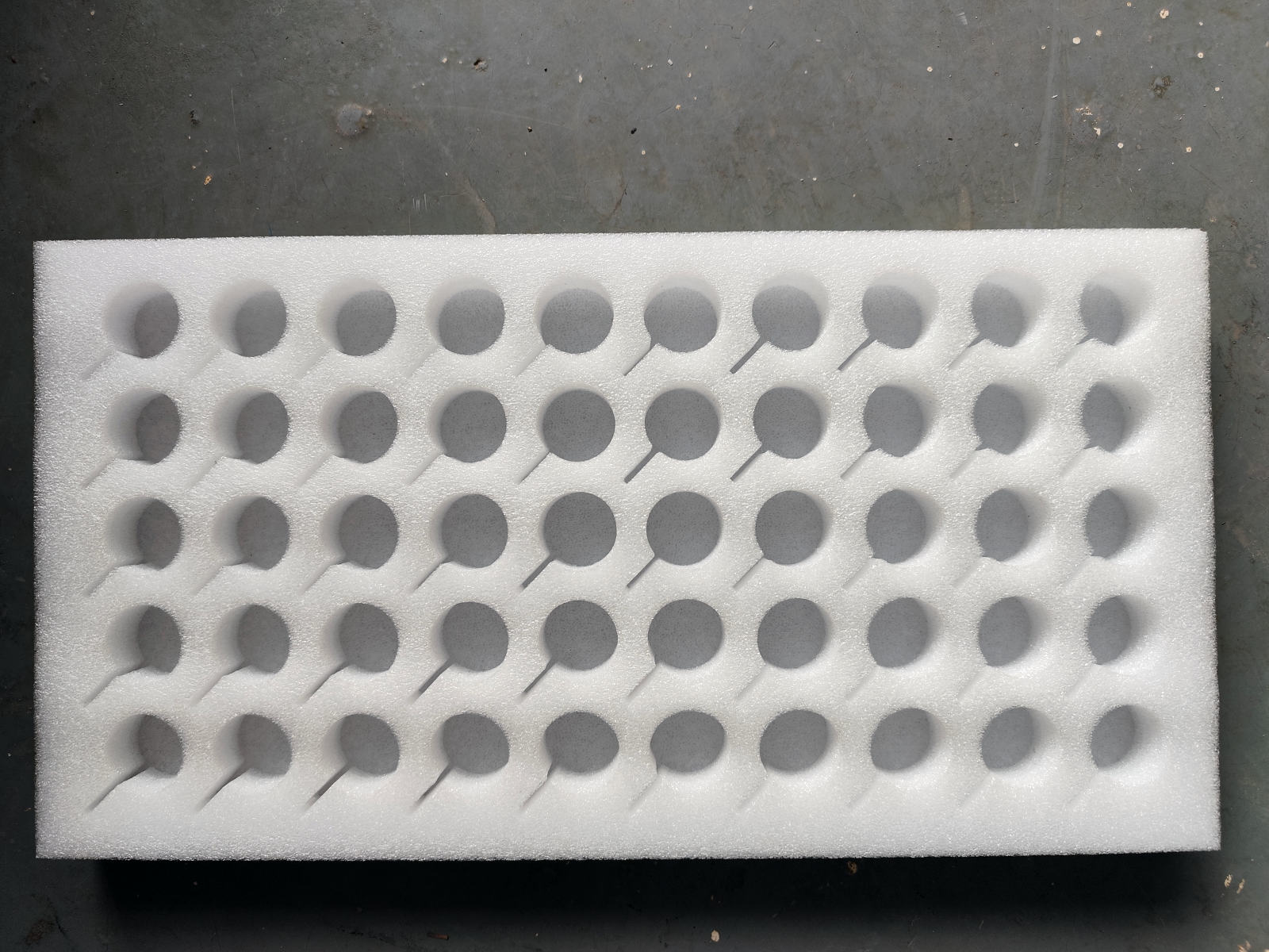
Define the Tray’s Job in the Supply Chain
A tray used between two factory processes is different from a tray used for export, retail presentation or returnable circulation. Start by identifying where the tray enters and leaves the process.
Clarify:
- whether the tray is for work-in-process, storage, shipment, presentation or a combination;
- the number of parts required per tray and per carton;
- whether operators load and unload by hand or with equipment;
- whether the tray is used once or returned for repeated cycles;
- the required stacking direction and maximum stack height;
- the carton, tote or container dimensions;
- the expected transport route and handling conditions;
- any cleanliness, identification or surface-contact requirement defined by the buyer.
These answers determine whether the priority is cushioning, separation, counting, presentation, fast picking or compact shipping.
Build the Cavity Around the Actual Part
Provide maximum part dimensions, tolerance, weight and orientation. If the component has threads, pins, connectors, polished faces or coated areas, show them on the drawing and identify which surfaces can safely contact foam.
Do not design only from one average sample. Repeated cavities make tolerance problems highly visible: if one part is slightly larger, the entire loading pattern may become slow; if parts are smaller, several positions may allow movement. Representative samples from the expected tolerance range are more useful than a single ideal part.
Include any bag, cap, film or protective sleeve that remains on the part. The final packed condition controls the cavity, not the bare product drawing alone.
Choose the Correct Cavity Count and Tray Size
Cavity count affects material use, operator movement, carton weight and line balance. A higher count is not automatically more efficient. A very large tray can flex during handling, become difficult to lift or create an inconvenient part quantity for the assembly process.
Review cavity count together with:
- the number of parts consumed at the next process step;
- safe and practical tray weight when fully loaded;
- carton or tote usable dimensions;
- operator reach and workstation space;
- inventory counting units;
- pallet and shipping configuration;
- the minimum foam required around the outer row.
A tray quantity that matches a production batch or assembly sequence can reduce recounting and partial trays. The buyer should define this operational preference before the supplier optimizes the cavity layout.
Set Pitch, Divider Width and Edge Distance
Together with EPE density and thickness, pitch is the center-to-center distance between repeated cavities. It must allow enough foam between adjacent items and enough material around the outside of the tray. The narrowest divider usually controls the local strength, especially when cavities have finger notches or irregular projections.
Check three dimensions separately:
- the minimum divider between cavities;
- the edge distance from the outer cavities to the tray perimeter;
- the base thickness beneath the deepest cavity.
Increasing cavity count by reducing every divider can produce a tray that looks efficient on a drawing but tears, bends or allows adjacent parts to touch. Layout efficiency should be confirmed with a physical loaded sample.
Design Removal Access for the Operator
Small parts can be difficult to remove from close-fitting cavities. Operators may pinch the foam, use an unsuitable tool or turn the tray over, which can damage the insert and slow the line. Plan removal access as part of the cavity geometry.
Finger notches
A side notch exposes a safe grip area. Its size should match the part and operator task without removing excessive divider material. In a dense array, notch direction can alternate or align to preserve stronger load paths.
Push-through or bottom access
Some tray systems permit access from below, but this depends on the base structure and how the tray is supported. The method should not allow parts to fall out during transport.
Controlled cavity depth
A shallow cavity improves access but may reduce retention. A deeper cavity controls movement but can hide the part or make removal harder. Select depth using the actual handling sequence and any top pad or cover.
Observe workers loading and unloading the sample when possible. A cavity that feels acceptable for one demonstration may become inefficient when repeated hundreds of times.

Use Color and Orientation to Support Inspection
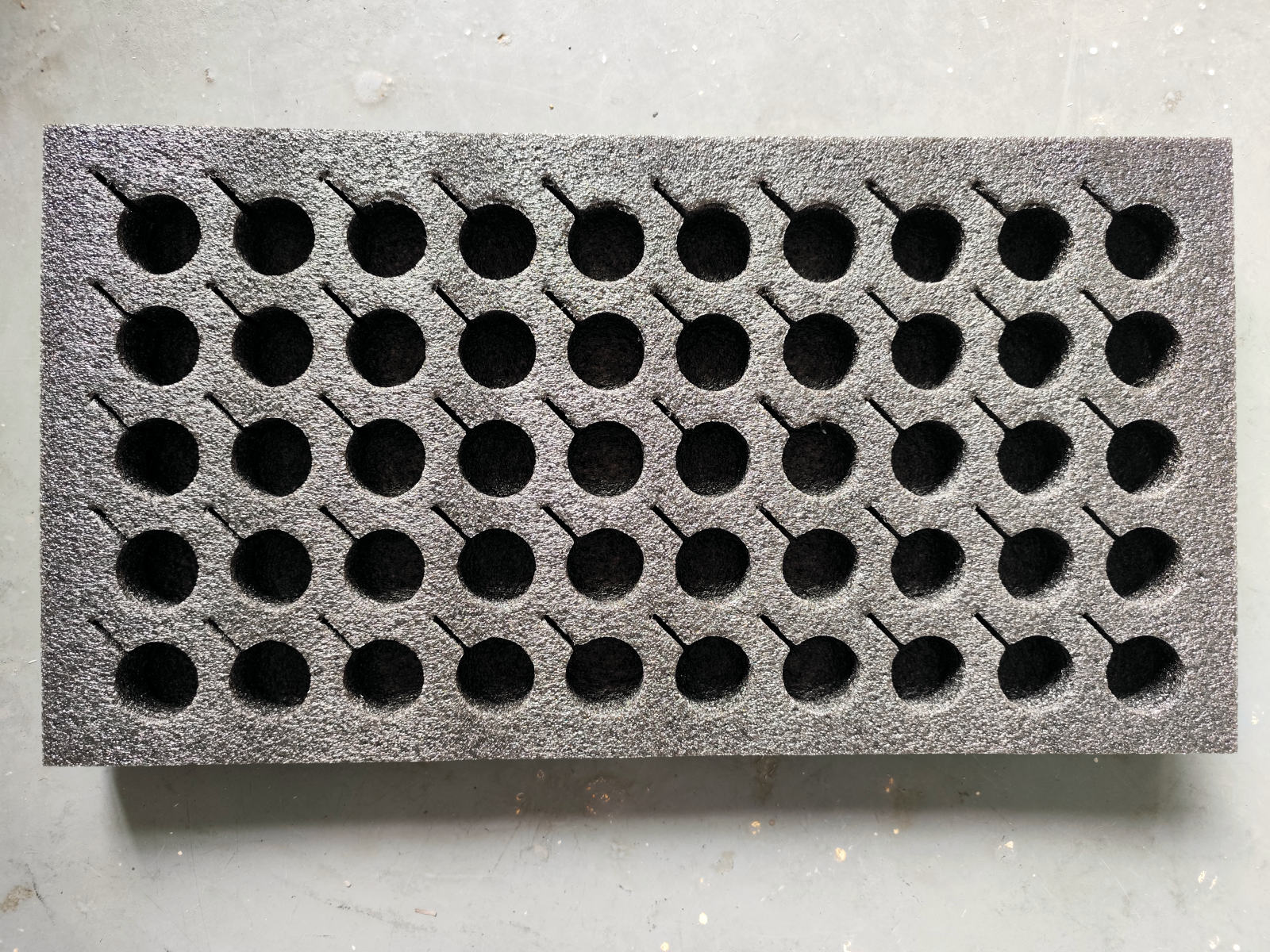
White and black EPE can both be made into multi-cavity trays. Color may influence contrast with the component, appearance and how easily marks are seen. It does not by itself define density, stiffness or electrical properties.
A high-contrast background can help operators notice an empty cavity or incorrectly oriented part. If orientation matters, use an asymmetric cavity feature, clear row direction or a packing diagram. Avoid relying only on subtle visual differences that disappear when the tray is full.
When electrostatic control or another special material function is required, state the required property and test or documentation criteria separately. Do not assume a tray has a functional property based only on its color.
Plan Stacking and Layer Separation
Loaded trays may be stacked directly, separated by a flat sheet or placed in individual cartons. The structure should prevent an upper tray from pressing on vulnerable parts below. Product height, cavity depth and tray base all affect the stack.
Confirm:
- whether the tray itself carries stacking load;
- whether parts project above the foam surface;
- the need for a top sheet, lid or separator;
- the total stack height and compression inside the carton;
- how workers align trays during packing;
- whether the bottom of one tray can mark the products below.
If the tray is returnable, also review how empty trays nest or stack, how they are cleaned under the buyer’s process and how damage is identified before reuse.
Integrate the Tray With Cartons, Totes and Workstations
The tray outside dimensions should match the usable internal space of the chosen container. Tote ribs, carton seams, handles and liners can reduce the nominal space. Provide actual usable dimensions and the intended loading direction.
For export cartons, calculate the complete packed quantity, gross weight and number of tray layers. Use suitable top and bottom protection where required and make sure carton compression is not transferred directly to projecting components.
At the workstation, review tray orientation, label position, operator reach and how empty trays are removed. Packaging that fits the shipping carton but disrupts the assembly sequence can add hidden labor cost.

Approve a Representative Multi-Cavity Sample
A useful sample should represent the final cavity pattern, divider widths, base thickness and outside dimensions. A small piece with only one cavity may confirm local fit but cannot show tray flex, counting layout or full-stack behavior.
Use this approval sequence:
- confirm the part revision, dimensions, tolerance and packed condition;
- load parts from different production lots where available;
- check fit across corner, edge and center cavities;
- observe loading and removal time for a complete tray;
- lift the loaded tray at the intended grip points and check flex;
- stack or separate trays in the planned configuration;
- place the complete stack in the carton or tote;
- record revisions and approve the final sample with the drawing.
If performance testing is required, the buyer should define the test method, packed configuration and acceptance criteria. Sample appearance alone does not demonstrate a specific transport performance.
Prepare a Complete RFQ for a Small-Parts Tray
Follow the EPE insert quotation checklist and send the factory enough information to quote the same structure you intend to approve:
- part drawing, maximum dimensions, tolerance and weight;
- clear photos showing fragile, sharp or no-contact features;
- representative samples where practical;
- required cavity count and preferred row-by-column arrangement;
- tray outside size or container usable dimensions;
- loading orientation and removal method;
- stacking, separator and top-pad requirements;
- quantity per carton, target order quantity and shipment destination;
- any material property, inspection or documentation requirement.
Ask the supplier to identify assumptions and separate components in the quotation. This prevents two quotations with different cavity counts, thicknesses or accessories from appearing directly comparable.
Define Batch Quality and Change Control
Repeated cavities need more than an outside-size inspection. Agree critical characteristics based on the part and process.
Possible checkpoints include:
- tray outside length, width and total height;
- cavity count, pitch, depth and critical opening dimensions;
- minimum divider, edge and base thickness;
- row alignment and orientation features;
- cut-edge condition, debris and visible marks;
- loaded tray fit and removal using representative parts;
- stack height and container fit;
- packing quantity and label position.
Part revisions should be reviewed before the next tray order. A small change to a thread, connector, cap or coating can affect dozens of cavities at once.
Reduce Cost by Improving the Complete Handling Unit
Cost reduction can come from a more efficient row layout, a tray count matched to the process, reduced unused border space, standardized cavities for shared parts or a better carton-to-tray ratio. Simplification should be reviewed on the loaded sample.
A cheaper tray is not a saving if it increases picking time, causes counting errors, tears during handling or requires a larger carton. Compare material, labor, handling and shipping effects together.
Discuss Your Small-Parts Tray With Shanghai Hongying
Shanghai Hongying can review component drawings, samples, tray quantities, container dimensions and line-handling requirements to discuss cavity layout, EPE structure, sample making and batch supply. Final dimensions and material choices should be confirmed with the buyer’s actual parts and process.
For a faster initial review, send the part file, tolerance range, required cavity count, tray or tote size, target quantity and photos of the loading and removal orientation.
FAQ
How many small parts should one EPE tray hold?
The best count depends on part size and weight, process batch quantity, operator handling, carton dimensions and the minimum foam required between cavities. Review the complete handling unit rather than maximizing count alone.
How tight should each cavity be?
Fit should control movement without slowing loading or damaging the part. The correct clearance or light interference depends on tolerance, surface sensitivity, foam behavior and the handling method, so it should be confirmed with representative samples.
Can a tray use both round and rectangular cavities?
Yes. A tray can organize different components, but each cavity needs suitable support, access and orientation. Mixed shapes should still preserve adequate dividers and a clear packing sequence.
Are black EPE trays automatically anti-static?
No. Color alone does not confirm an electrical property. If electrostatic control is required, specify the property and agreed verification or documentation separately.
Should small-parts trays have finger notches?
They are useful when a close or deep cavity makes removal difficult. Notch size and direction should support the operator without weakening the divider excessively.
What should be approved before batch production?
Approve the part revision, cavity count and layout, fit, removal method, EPE description, tray dimensions, stacking method, carton or tote fit, physical sample and agreed inspection points.